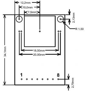
Arducam Shield Mini 5MP Plus
1. Introduction
ArduCAM Shield Mini 5MP Plus is the latest version compared to its predecessor ArduCAM-M-5MP. It is a general purpose high definition 5MP SPI camera, which reduces the complexity of the camera control interface. It integrates 5MP CMOS image sensor OV5642 and provides miniature size, as well as an easy-to-use hardware interface and open source code library. This camera can be used on any platform like Arduino, Raspberry Pi, Maple, Chipkit, Beaglebone black, as long as they have SPI and I2C interface and can be well mated with standard Arduino boards. ArduCAM mini not only offers the capability to add a camera interface that doesn’t have in some low-cost microcontrollers but also provides the capability to add multiple cameras to a single microcontroller.
2. Feature
- 5MP image sensor OV5642
- M12 mount or CS mount lens holder with changeable lens options
- IR sensitive with proper lens combination
- I2C interface for the sensor configuration
- SPI interface for camera commands and data stream
- All IO ports are 5V/3.3V tolerant
- Support JPEG compression mode, single and multiple shoot mode, one-time capture multiple read operation, burst read operation, low power mode and etc.
- Well mated with standard Arduino boards
- Provide open source code library for Arduino, STM32, Chipkit, Raspberry Pi, BeagleBone Black
- Small form of factor
3. Key Specifications
| Power Consumption Normal :5V/300mA Low power mode: 5V/20mA | Active pixel size: 2592x1944 |
|---|---|
| SPI speed: 8MHz | Lens: 1/4 inch |
| Frame buffer: 8MByte | Resolution support: 5MP, 1080P, 720P, VGA, QVGA |
| Format support: YUV, JPEG | Size: 34 x 24 mm |
| Weight: 30g | Temperature: -10℃~+55℃ |
4. Pin Definition
| Pin No. | PIN NAME | TYPE | DESCRIPTION |
|---|---|---|---|
| 1 | CS | Input | SPI slave chip select input |
| 2 | MOSI | Input | SPI master output slave input |
| 3 | MISO | Output | SPI master input slave output |
| 4 | SCLK | Input | SPI serial clock |
| 5 | GND | Ground | Power ground |
| 6 | VCC | POWER | 3.3V ~ 5V Power supply |
| 7 | SDA | Bi-directional | Two-Wire Serial Interface Data I/O |
| 8 | SCL | Input | Two-Wire Serial Interface Clock |
5. Functions
5.1 Single Capture Mode
Single capture mode is the default capture mode of the camera. After issuing a capture command via SPI port, the ArduCAM will wait for a new frame and buffer the one entire image data to the frame buffer, and then assert the completion flag bit in the register. The user only needs to poll the flag bit from the register to check out if the capture is done.
5.2 Multiple Capture Mode
Multiple capture mode is advanced capture mode. By setting the number of frames in the capture register, the ArduCAM will capture consequent frames after issuing the capture command.
5.3 Short Movie Recording Mode
Short movie recording mode is advanced capture mode. By setting the maximum number of frames in the corresponding register, the ArduCAM will capture continuous frames until the 8MByte frame buffer is full.
5.4 JPEG Compression
The JPEG compression function is implemented in the image sensor. With proper register settings to the sensor, the user can get different resolutions with JPEG image stream output.
5.5 Normal Read and Burst Read Operation
Normal read operation reads each image data by sending a read command in one SPI read operation cycle. While burst read operation only needs to send a read command and then read multiple image data in one SPI read operation cycle. It is recommended to use burst read operation to get better throughput performance.
5.6 Rewind Read Operation
Sometimes user wants to read the same frame of image data multiple times for processing, the rewind read operation is designed for this purpose. By resetting the read pointer to the beginning of the image data, the user can read the same image data from the start point again.
5.7 Low Power Mode
Some battery power devices need to save power when in the idle status, the ArduCAM offers the low power mode to reduce power consumption, by shutting down the sensor and memory circuits.
5.8 Image Sensor Control
Image sensor control function is implemented in the image sensor. By setting the proper set of register settings, the user can control the exposure, white balance, brightness, contrast, color saturation and etc.
6. Hardware Wiring
6.1 Single Camera Wiring
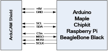
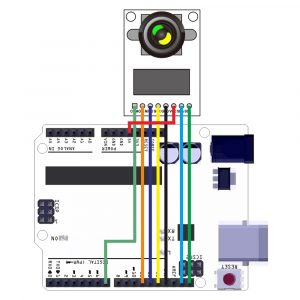
The typical connection between ArduCAM shield and Arduino or etc platform is shown in Figure 1. More typically Figure 2 shows the wiring for the Arduino UNO R3 board.
Figure 1 Typical Wiring
Figure 2 Wiring for Arduino UNO R3
6.2 Multi Cameras Wiring
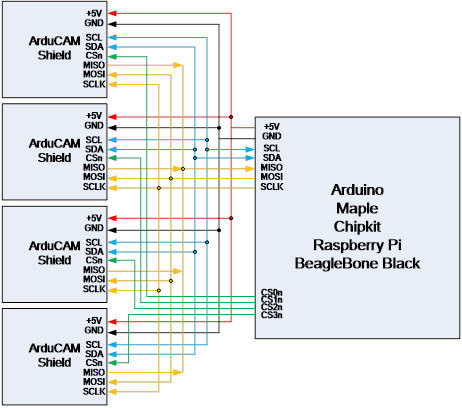
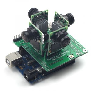
The multi-cameras connection between ArduCAM shield and Arduino or etc platform is shown in Figure 3. More typically Figure 4 shows the multi-cameras wiring for Arduino UNO R3 board.
Figure 3 Multi-Cameras Wiring
Figure 4 Mult-Cameras Wiring on Arduino UNO
7. I2C Interface
The I2C interface is directly connected to the image sensor OV5642. It should be well initialized before a normal operation, or else there is no output from the sensor. The OV5642 I2C slave address is 0x78 for writing and 0x79 for reading. Users can use the I2C master to read and write all the registers in the OV5642 sensor. For more information about the OV5642 register, please refer to the OV5642 datasheet. Figure 5 shows the writing value 0x80 to the OV5642 register 0x3008. Figure 6 shows reading value 0x56 from the OV5642 register 0x300A.
Figure 5 I2C Write Bus Timing
Figure 6 I2C Read Bus Timing
8. SPI Slave Interface
The ArduCAM SPI slave interface is fixed SPI mode 0 with POL = 0 and PHA = 0. The maximum speed of SCLK is designed for 8MHz, care should be taken not to overclock the maximum 8MHz. The SPI protocol is designed with a command phase with a variable data phase. The chip select signal should always keep asserted during the SPI read or write bus cycle. For SPI detail timing, please continue to read Arduchip chapter.
9. Lens Options
The ArduCAM Shield Mini 5MP Plus camera shield is shipped with default LS-27227 (S mount). There are more lens options which can be found from our lens product page.
