Raspberry Pi Camera Pinout
General Introduction
There are two different kinds of Raspberry Pi standard MIPI-csi camera connectors: 15pin and 22-pin. The 15pin connector is mostly seen on standard Raspberry Pi models (A&B series) and Pi camera modules; That of 22-pin is on Raspberry Pi 5, Pi Zero Series and Compute Module IO Board. Arducam also uses derived versions of these connectors, usually with different FPC contact positions, to accommodate different camera board designs.
Connector Types and Part Number
Raspberry Pi Platform and camera Connectors Type:
| Location | Part Number | Manufacturer | Mounting Angle | No. of Pins | Pitch |
|---|---|---|---|---|---|
| Camera Module (V1/V2/HQ) | SFW15R-2STE1LF | Amphenol FCI | Right Angle | 15 | 1mm |
| Camera Module (V3) | F32Q-1A7H1-11022 | Amphenol Aorora | Right Angle | 22 | 0.5mm |
| Pi Board (As & Bs) | 1-1734248-5 | TE Connectivity | Vertical | 15 | 1mm |
| Pi Board (Zero & Zero W & Zero 2 W) | WM8828DKR-ND | Molex | Right Angle | 22 | 0.5mm |
Available Cables
Browse all available mipi-csi cables from Arducam here: Arducam Archive - Camera Cable
15-15pin Connector
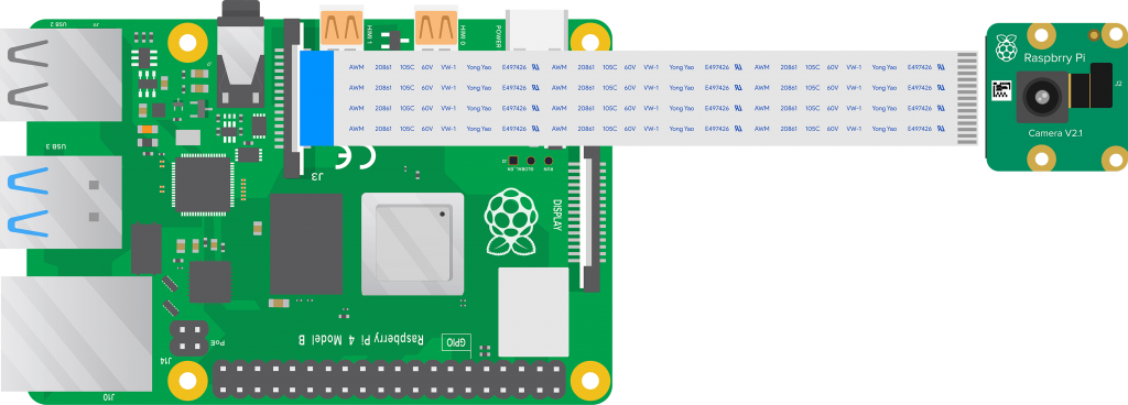
The 15-15 pin connector is the most used one on the previous cameras and platforms. Unless otherwise indicated, It’s the “default” connector in terms of Raspberry Pi camera. You will see it in mainstream Raspberry Pi products such as the Model A&B series as well as V1&V2 camera modules.
The double
15in 15-15pin refer to the 15-pin connectors on the platform (such as the Raspberry Pi 4B) connector and the camera connector (such as RPI V1/V2).
Camera Board Connector
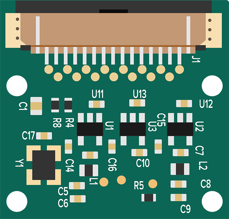
Connector on the V1.3 or V2.1 Pi Camera Board:
 |
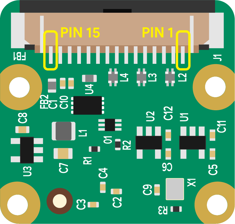 |
It is a 1.0mm pin pitch 15-position right angle and lower contact FFC or FPC connector.
Connector PN: SFW15R-2STE1LF
See Connector Datasheet Here: Datasheet - SFW15R-2STE1LF
Raspberry Pi Board Connector
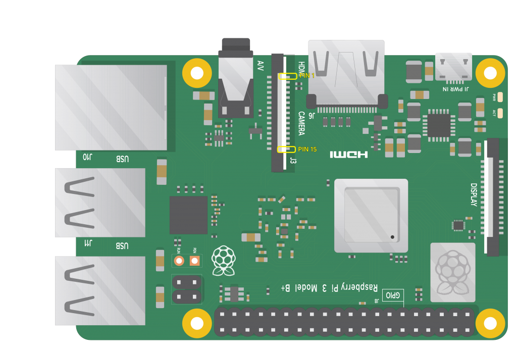
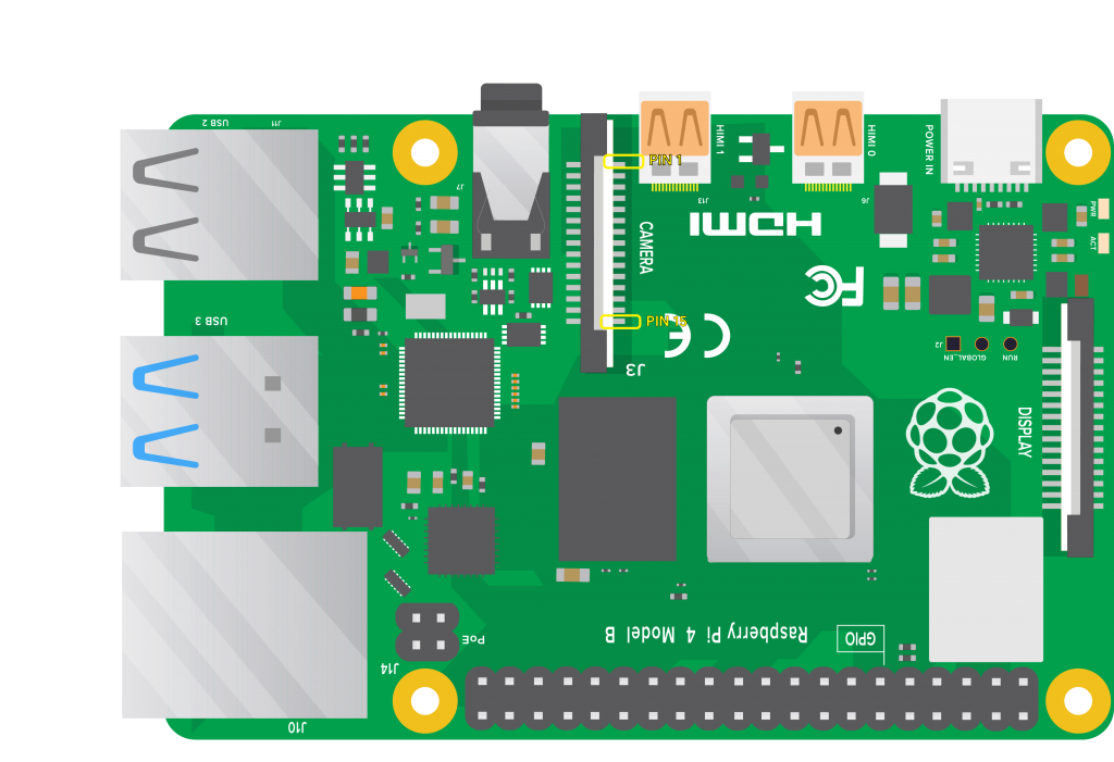
Connector on the Raspberry Pi Model A and B or B Plus:
 |
 |
Derived or Alternative Connector
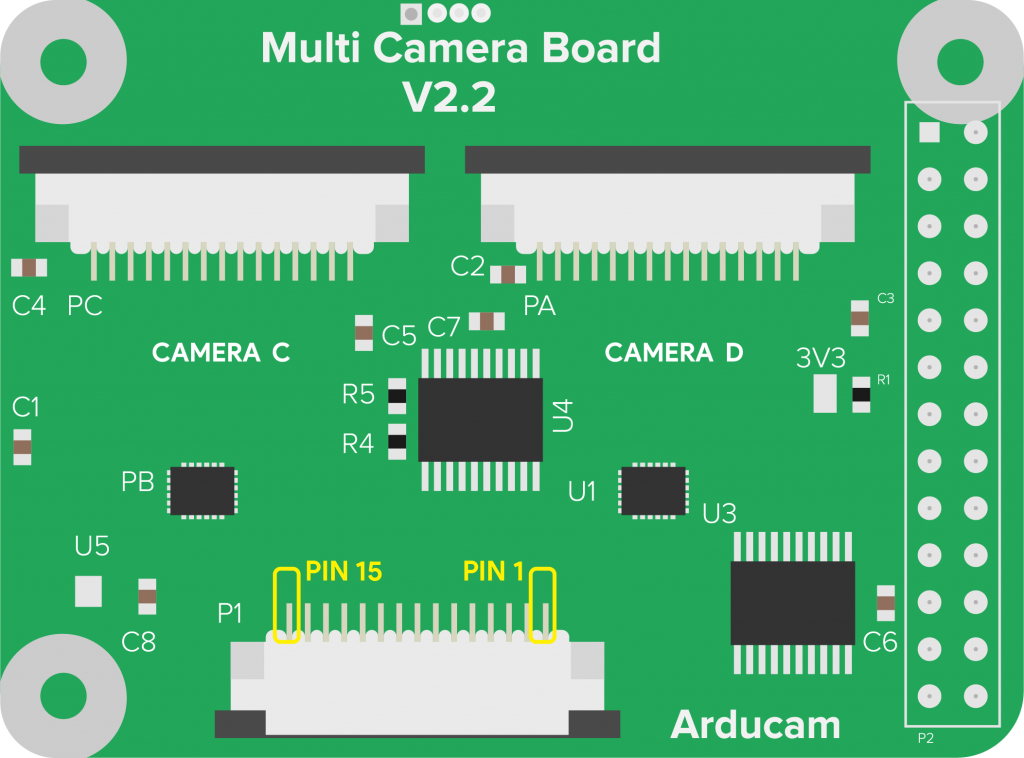
Derived or Alternative Connectors on Arducam Raspberry Pi Camera Products:
 |
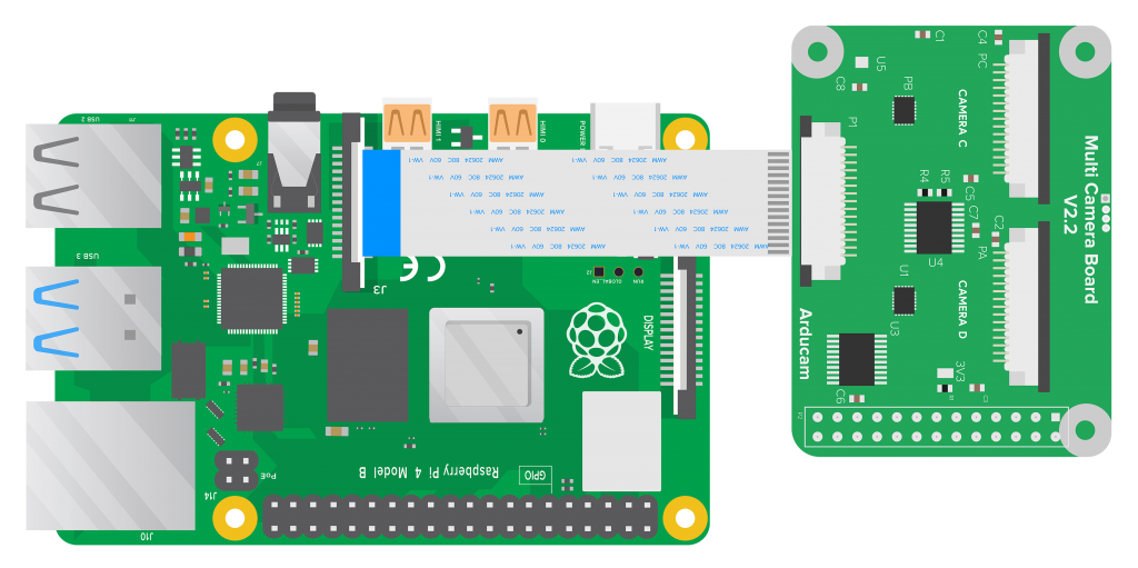 |
Apart from the two 15-pin connectors above, Arducam also uses a derived version with an upper contact. Its FPC contact part is on the upper side other than the camera board side.
Raspberry Pi 15pin MIPI-CSI Connector Pinout
Pinout Note
No matter what type of the connector model is, the pinout for these camera connectors is the same.
The following table is the pin definition of the camera board, the signals are input or output type. Vice versa these pins on the RPI board are in reverse direction.
| Pin # | Name | Description |
|---|---|---|
| 1 | GND | Ground |
| 2 | CAM_D0_N | MIPI Data Lane 0 Negative |
| 3 | CAM_D0_P | MIPI Data Lane 0 Positive |
| 4 | GND | Ground |
| 5 | CAM_D1_N | MIPI Data Lane 1 Negative |
| 6 | CAM_D1_P | MIPI Data Lane 1 Positive |
| 7 | GND | Ground |
| 8 | CAM_CK_N | MIPI Clock Lane Negative |
| 9 | CAM_CK_P | MIPI Clock Lane Positive |
| 10 | GND | Ground |
| 11 | CAM_IO0 | Power Enable |
| 12 | CAM_IO1 | LED Indicator |
| 13 | CAM_SCL | I2C SCL |
| 14 | CAM_SDA | I2C SDA |
| 15 | CAM_3V3 | 3.3V Power Input |
15-22pin Connector
Tip
The 15-22pin MIPI-csi connector refers to a connector with a 1mm pitch 15pin transmission channel on one end and a 0.5mm fine pitch 22-bit lower (or bottom) contact FFC or FPC on the other end.
Connector on Raspberry Pi 5
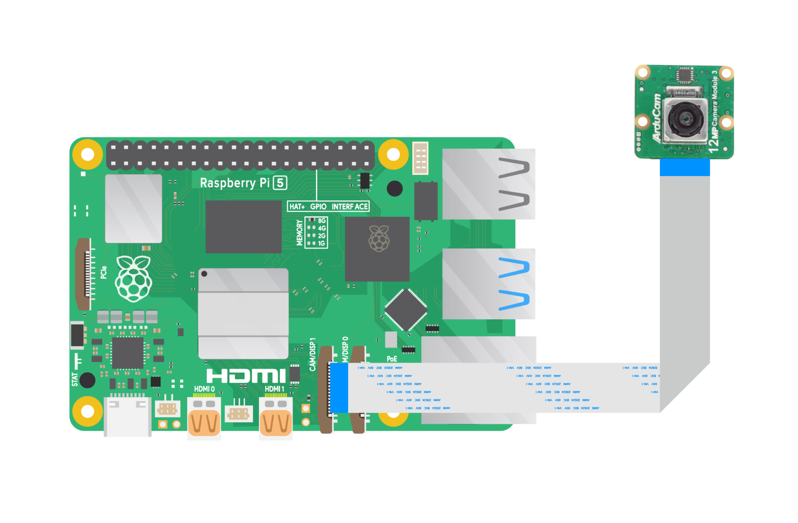
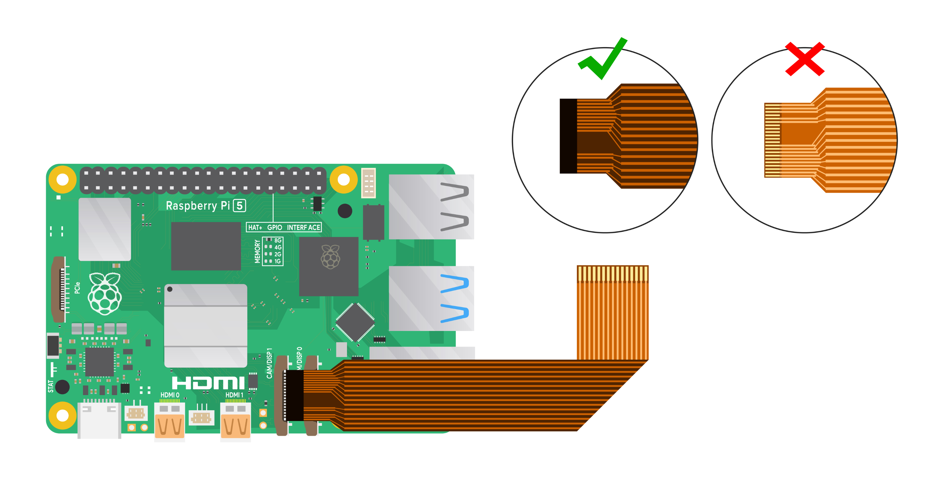
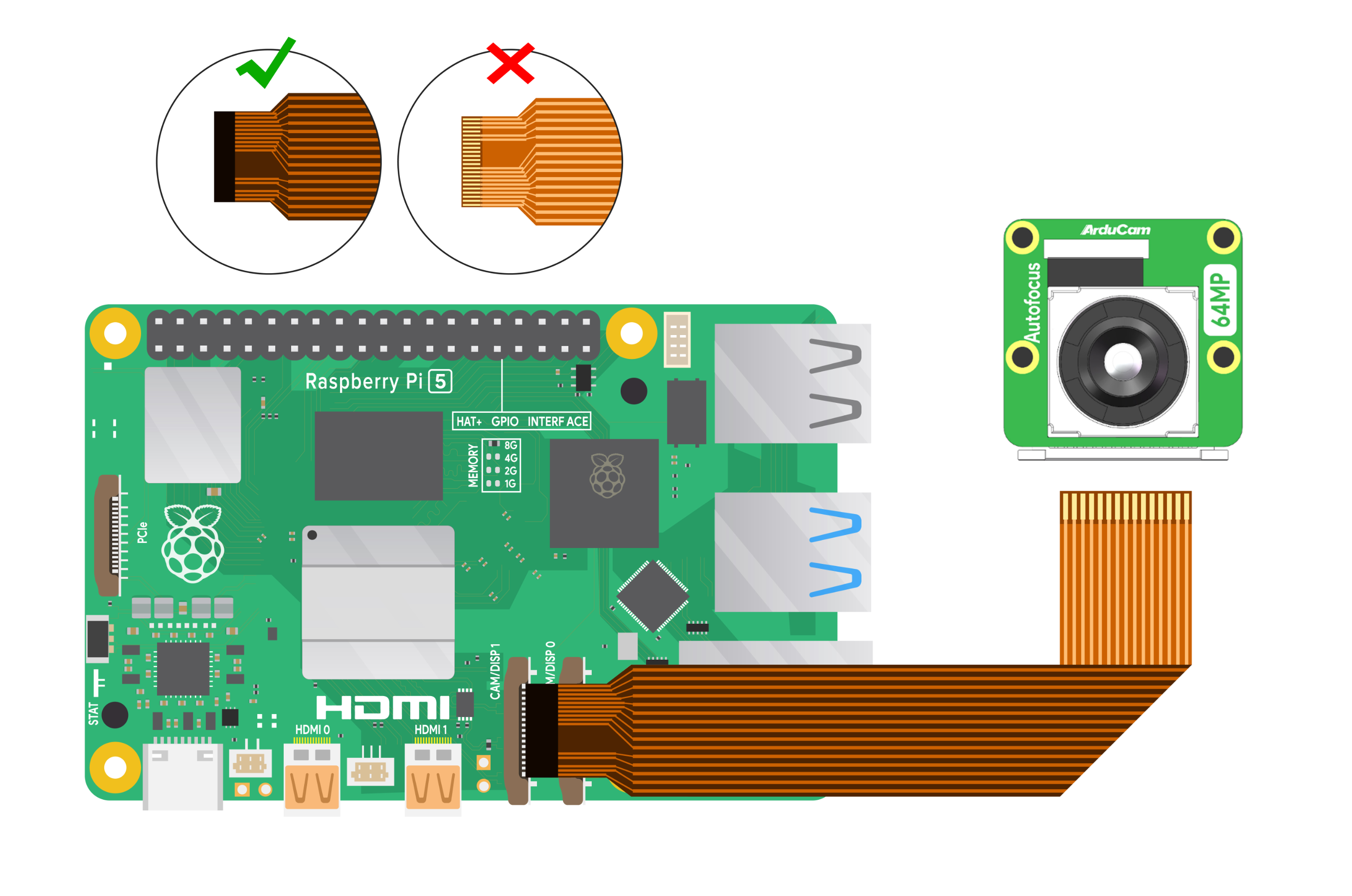
The following diagrams show a Raspberry Pi 5 and an Arducam 64MP OV64A40 camera connected using a 15-22pin FPC cable. The MIPI-csi connector of the Raspberry Pi 5 is 22pin, while the Arducam 64MP OV64A40 camera uses a 15pin connector.
- 15pin-22pin Connection
 |
 |
Connector on Raspberry Pi 3/4
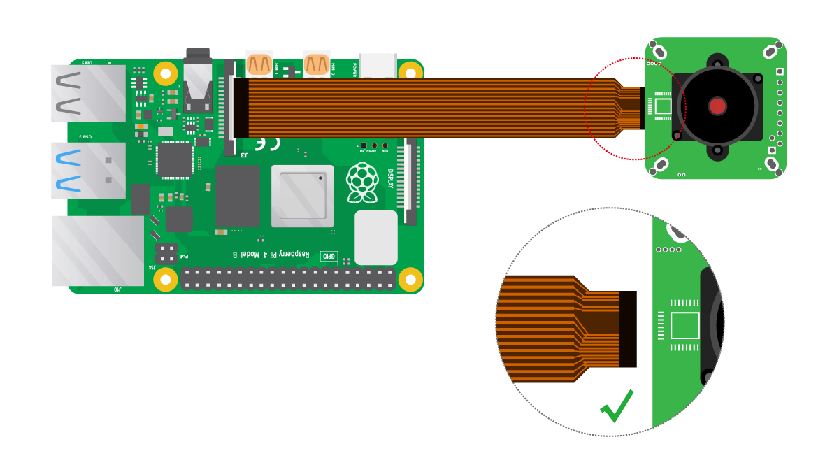
The following diagram shows a Raspberry Pi 4B and an Arducam 12MP IMX477 camera connected using a 15-22pin FPC cable. The MIPI-csi connector of the Raspberry Pi 4B is 15pin, while the Arducam 12MP IMX477 camera equips a 22pin connector.
Connector on Raspberry Pi Zero W
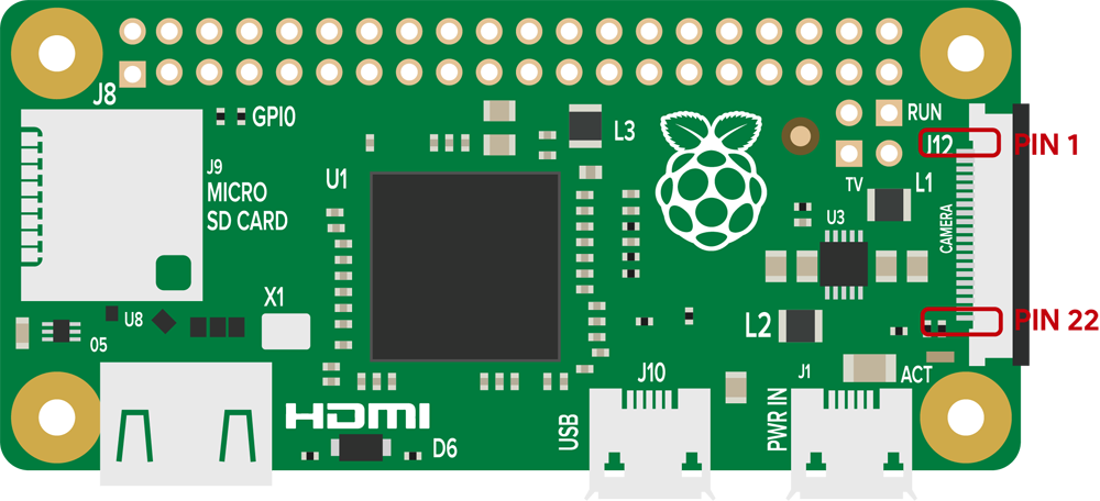
The following diagram shows a Raspberry Pi zero w and a RPI V2 camera connected using a 15-22pin FPC cable. The MIPI-csi connector of the Raspberry Pi zero w is 22pin, while the v2 camera uses a 15pin connector.
Connector on Raspberry Pi Compute Module IO Board
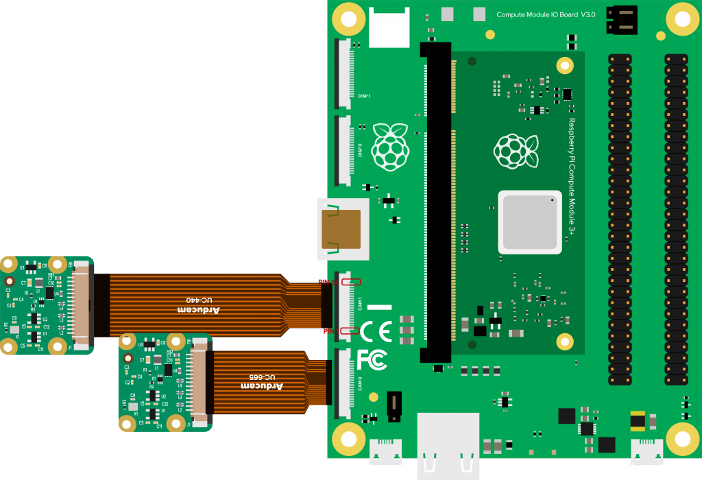
The following diagram shows a Raspberry Pi CM3 and a RPI V2 camera connected using a 15-22pin FPC cable. The MIPI-csi connector of the Raspberry Pi CM3 is 22pin, while the v2 camera uses a 15pin connector.
Raspberry Pi 22pin MIPI-CSI Connector Pinout
Tip
The 15pin MIPI-csi pinout is the same as the message described before, refer to: 15pin MIPI-csi Connector Pinout
For the 22pin MIPI-csi pinout information, please refer to the following table:
The following table is the pin definition on 22pin MIPI-csi connector pinout.
| Pin # | Name | Type | Description |
|---|---|---|---|
| 1 | GND | Ground | Power Ground |
| 2 | CAM_D0_N | Output | Pixel Data Lane0 Negative |
| 3 | CAM_D0_P | Output | Pixel Data Lane0 Positive |
| 4 | GND | Ground | Power Ground |
| 5 | CAM_D1_N | Output | Pixel Data Lane1 Negative |
| 6 | CAM_D1_P | Output | Pixel Data Lane1Positive |
| 7 | GND | Ground | Power Ground |
| 8 | CAM_CK_N | Output | Pixel Clock Output Form Sensor Negaitive |
| 9 | CAM_CK_P | Output | Pixel Clock Output Form Sensor Positive |
| 10 | GND | Ground | Power Ground |
| 11 | CAM_D2_N | Output | Pixel Data Lane2 Negative |
| 12 | CAM_D2_P | Output | Pixel Data Lane2 Positive |
| 13 | GND | Ground | Power Ground |
| 14 | CAM_D3_N | Output | Pixel Data Lane3 Negative |
| 15 | CAM_D3_P | Output | Pixel Data Lane3 Positive |
| 16 | GND | Ground | Power Ground |
| 17 | POWER-EN | Input | Power Enable |
| 18 | LED-EN | I/O | LED Enable/XCLK |
| 19 | GND | Ground | Power Ground |
| 20 | SCL | Input | SCCB serial interface clock input |
| 21 | SDA | I/O | SCCB serial interface data I/O |
| 22 | VCC | Power | 3.3V Power Supply |
22-22pin Connector
Instance on Raspberry Pi 5
The 22-22pin FPC Cable is usually used when the MIPI-csi interface on the camera and platform are both 22-pin, such as the Arducam IMX708 AF Camera and Raspberry Pi 5 in the figure below.
Instance on Raspberry Pi Zero
Statement
As shown in the pictures below, on the left are two types of MIPI-csi cables with 22-pin output channels. The yellow cable is a 15-22-pin cable (the narrower end is 22-pin and the wider end is 15-pin); the white cable is a 22-22-pin cable.
The figures below are the combination of Arducam IMX708 AF Camera and Raspberry Pi zero.
 |
 |
Connector pinout
Please refer to the following parts for specific connector pinout:
Troubleshooting
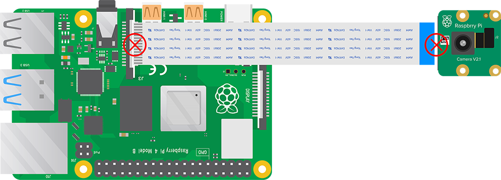
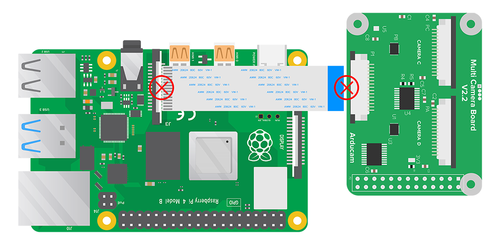
The following illustrations show the part of the WRONG ways to connect the camera cable. Make sure you are not connecting the camera cable in the following ways if you encounter any problem while using the camera.
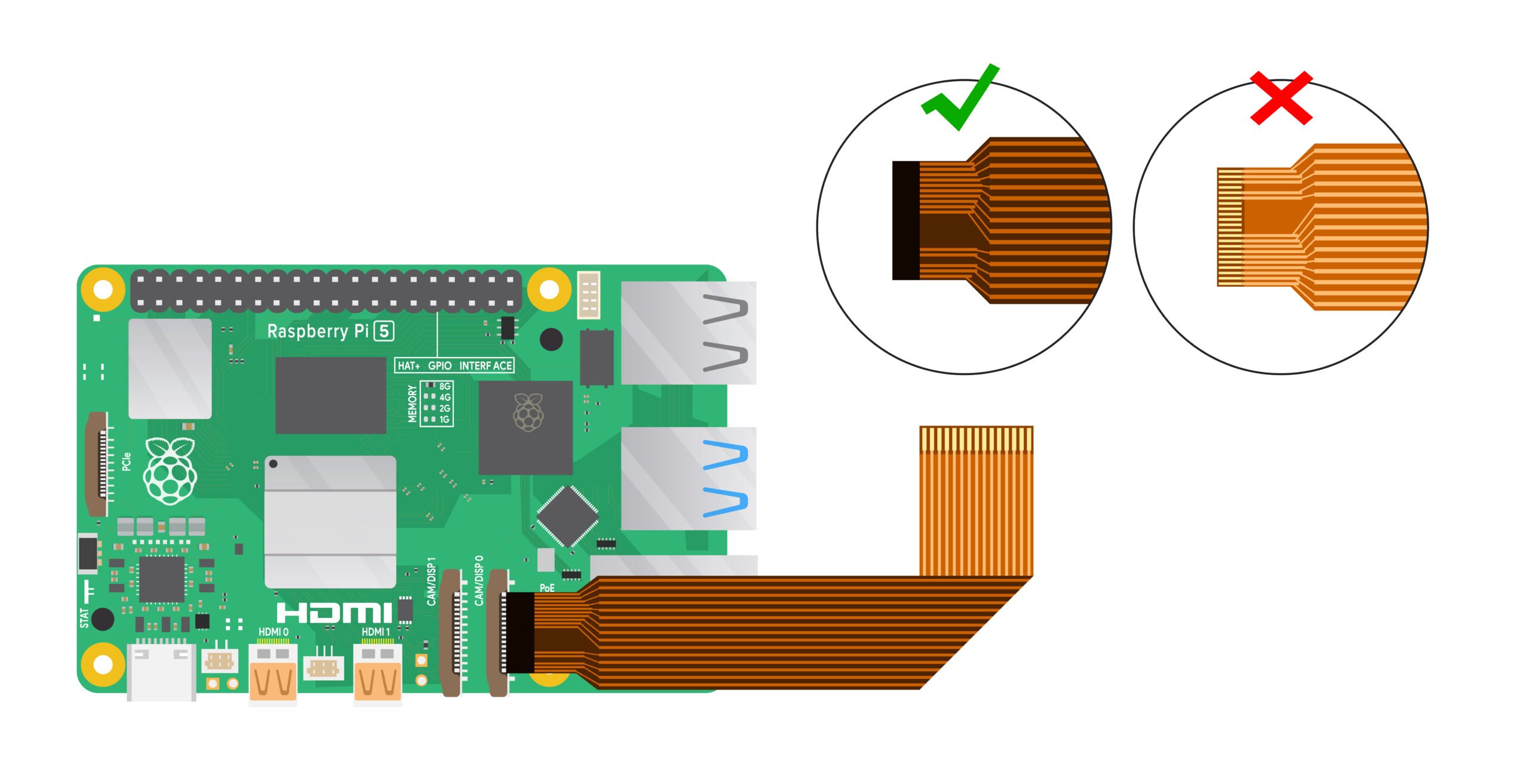
Cable to Pi 5: Gold contacts facing up, WRONG
Cable to Pi 3, Pi4: Silver contacts facing audio jack, WRONG
Cable to Pi Zero: Gold contacts facing up, WRONG
Cable to Arducam camera multiplexer: Input contacts facing PCB, WRONG
