Quick Start Guide
Overview
This guide provides step-by-step instructions for connecting your Arducam camera to a Raspberry Pi. The process involves two main components: hardware setup and software configuration. Follow this guide carefully to ensure proper camera functionality.
Hardware Setup
Step 1: Safety First - ESD Protection
⚠️ CRITICAL: Prevent Camera Damage
Camera modules are extremely sensitive to electrostatic discharge (ESD).
Before handling your camera:
- Use an anti-static wrist strap (recommended)
- Or touch a grounded metal object (faucet, computer case, etc.)
Never handle the camera PCB without proper grounding!
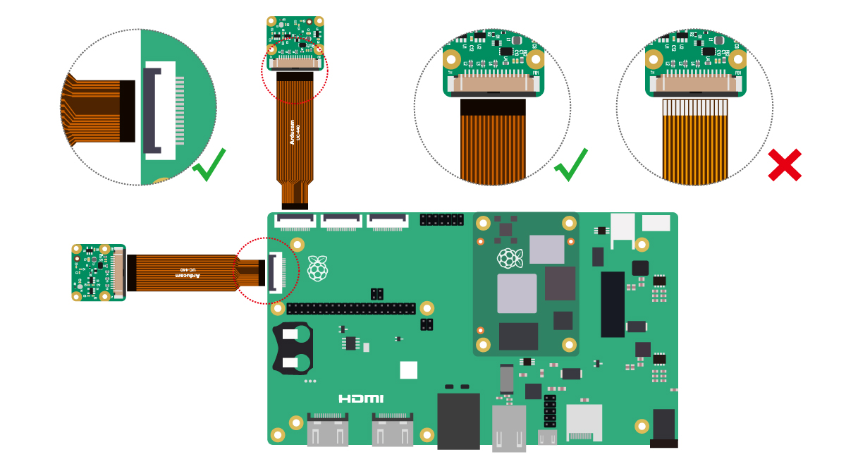
Step 2: Understanding Camera Connectors
The connection between your Raspberry Pi and camera module uses a flexible ribbon cable via the CSI (Camera Serial Interface) port.
The Golden Rule
Metal contacts on the flex cable must align and press against the metal contacts inside the connector.
Misalignment is the most common cause of connection issues.
Connector Types
CSI connectors come in two main types based on contact location:
| Connector Type | Cable Orientation | Description |
|---|---|---|
| Top-Contact | Contacts face DOWN | Most common on Arducam modules |
| Bottom-Contact | Contacts face UP | Standard Raspberry Pi cameras |

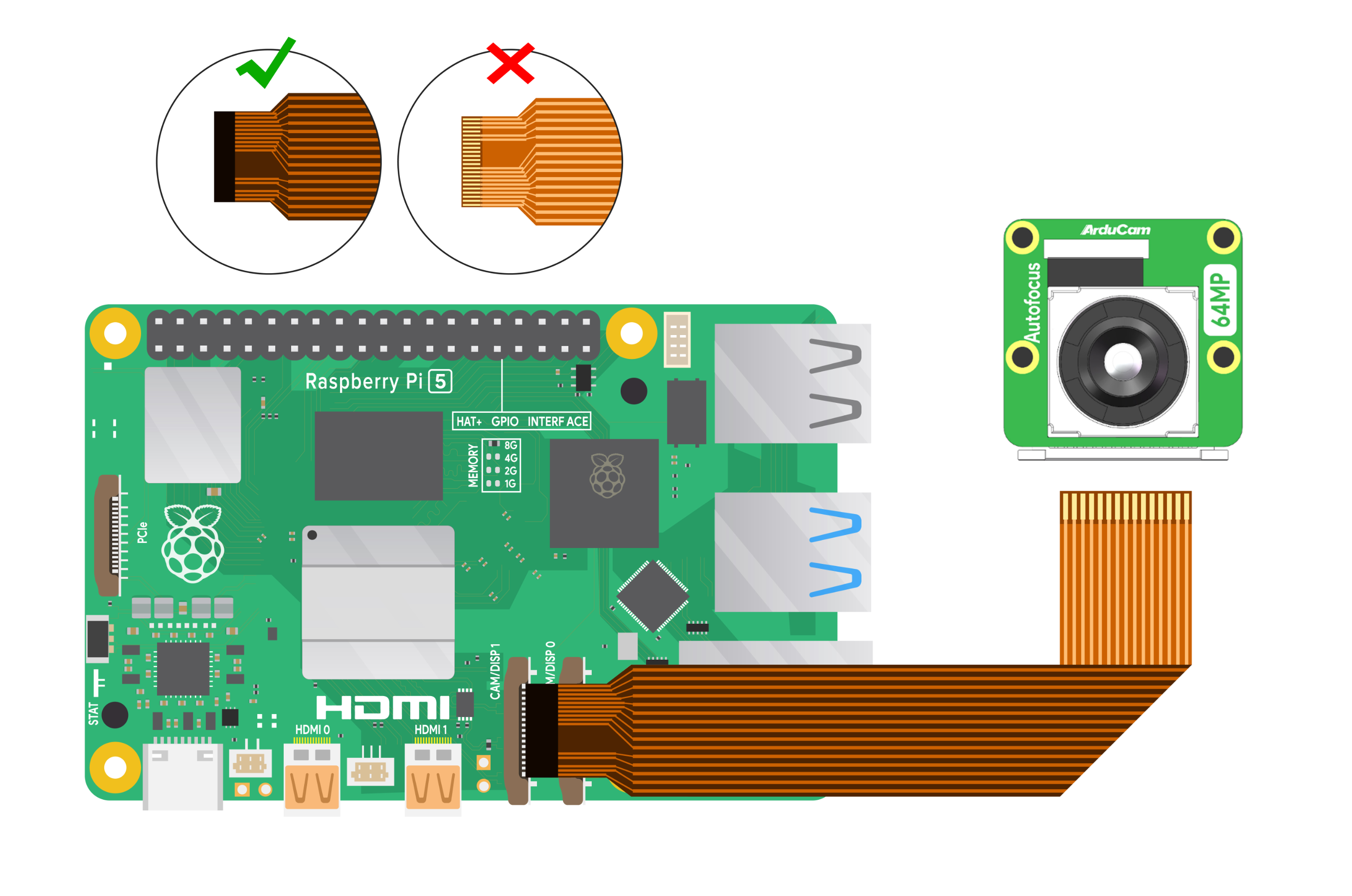
Left: 22-pin Top-Contact connector. Right: 15-pin Bottom-Contact connector.
Step 3: Connect to Raspberry Pi
Important
Always verify your specific camera model's connector type before connecting. The diagrams below show Pi-side connections only.
Select your Raspberry Pi model for specific connection instructions:
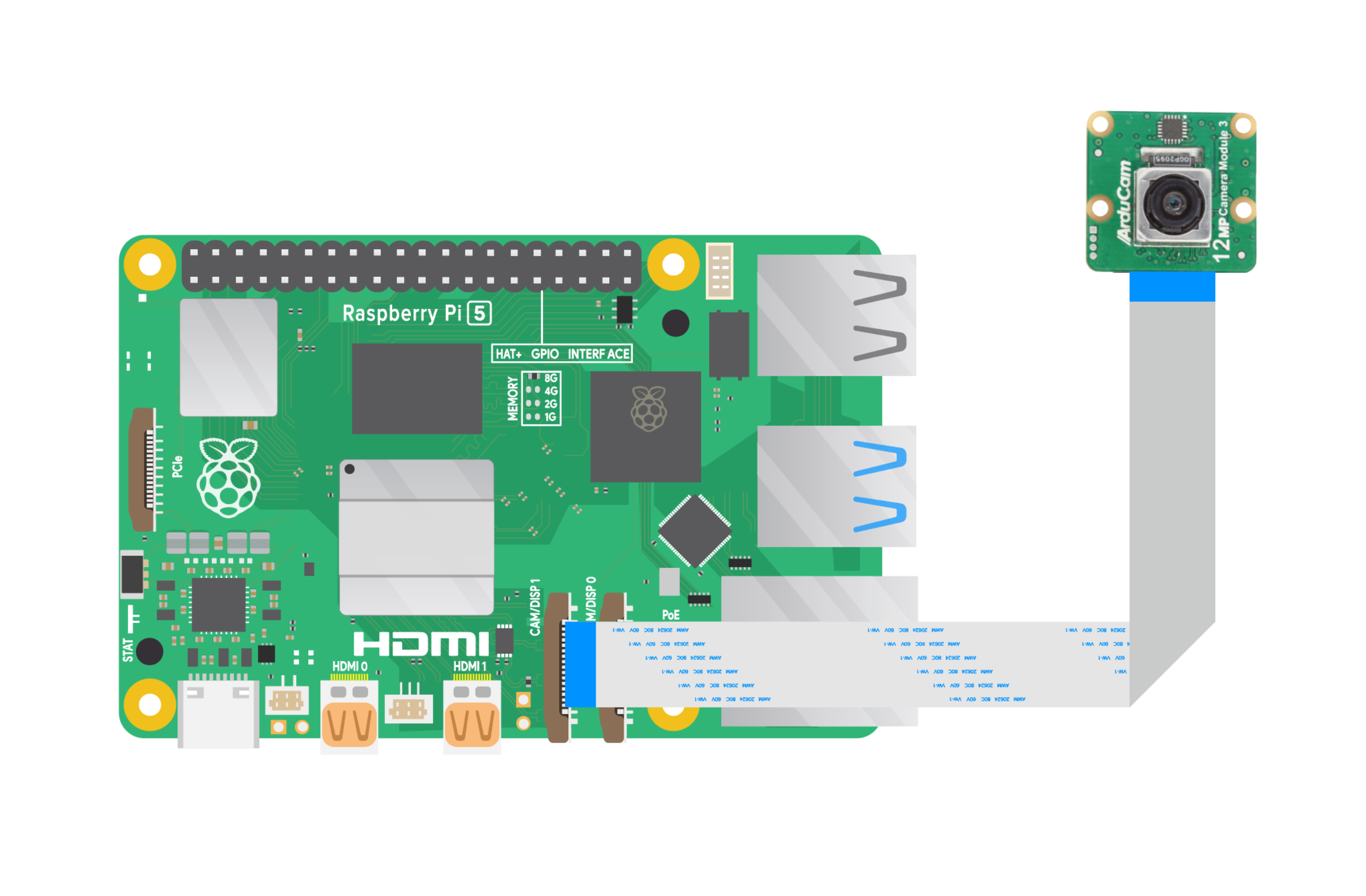
Location: Two CSI connectors between Ethernet and HDMI ports
Cable Orientation: Metal contacts face Ethernet port
The Pi 5 features dual camera ports, both requiring the cable's metal contacts to face the Ethernet port.
-
15-to-22-pin Connection
-
22-to-22-pin Connection
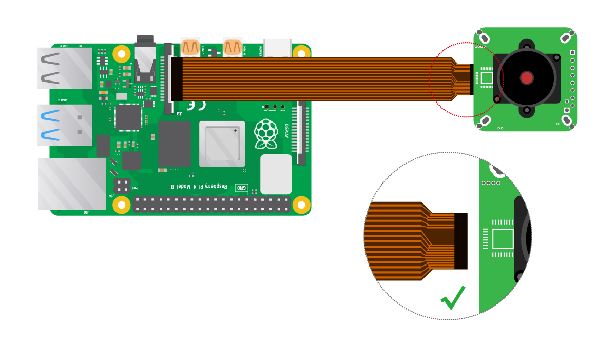
Location: Single CSI connector between Ethernet and HDMI ports
Cable Orientation: Metal contacts face HDMI port
-
15-pin to 15-pin Connection
Standard connection for most cameras.

-
15-pin to 22-pin Connection
For cameras with 22-pin connectors.
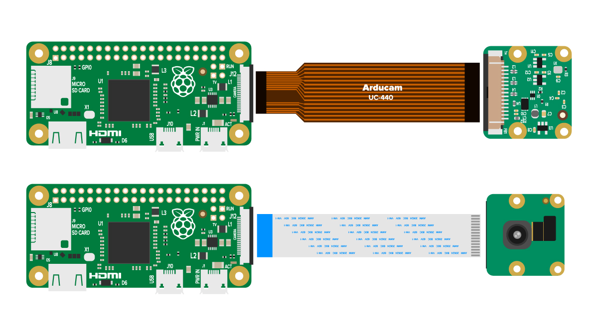
Location: Side-mounted camera connector
Cable Orientation: Metal contacts face DOWN (towards main board)
ZIF Connector Instructions
For Compute Modules (CM3/4/5):
- Open: Gently lift the black locking tab
- Insert: Slide cable firmly into connector
- Lock: Push tab back down to secure
For Pi Zero: Standard insertion method applies.
-
Pi Zero / Zero 2 W Connection
-
Compute Module IO Board
Software Configuration
Step 4: Find Your Camera's Software Guide
After completing hardware setup, locate your camera sensor below for specific software configuration instructions.
| Resolution | Sensor | Software Guide |
|---|---|---|
| 5MP | OV5647 | OV5647 Setup |
| 8MP | IMX219 | IMX219 Setup |
| 12MP | IMX477 | IMX477 Setup |
| 12MP | 477M | 477M Setup |
| 12MP | IMX708 | IMX708 Setup |
| 12MP | IMX378 | IMX378 Setup |
| 16MP | IMX519 | IMX519 Setup |
| 64MP | Hawkeye | 64MP Hawkeye Setup |
| 64MP | OV64A40 | OV64A40 Setup |
| 0.3MP | OV7251 | OV7251 Setup |
| 1.58MP | IMX296 | IMX296 Setup |
| 1MP | OV9281 | OV9281 Setup |
| 2MP | OV2311 | OV2311 Setup |
| 2MP | IMX290/462/327 | Starvis Setup |
Additional Resources
Raspberry Pi Model Reference
Platform Specifications
| Model | SoC | Memory | GPIO | Image |
|---|---|---|---|---|
| Raspberry Pi 5 | BCM2712 | 4GB/8GB | 40-pin |  |
| Raspberry Pi 4B | BCM2711 | 1-8GB | 40-pin |  |
| Raspberry Pi 3B+ | BCM2837b0 | 1GB | 40-pin |  |
| Raspberry Pi Zero 2 W | RP3A0 | 512MB | 40-pin (unpopulated) |  |
| Compute Module 3 | BCM2837 | 1GB | — |  |
| Compute Module 4 | BCM2711 | 1-8GB | — |  |
For detailed specifications, visit the Raspberry Pi official documentation.